Each of the main stringers, the front to back bits that fit in the frames and give the hull support and shape until finished, is made up of three pieces of 20mm x 25mm Clear Hoop Pine. The designer said it was easier to laminate them in place from three pieces rather than try and bend a 60mm x 25mm piece of wood around the curves. Having started on the first one, I believe him.
There are three main ones each side. The top and bottom, and a middle one which is located where the two curved sections meet. It will become clear hopefully as the photos and chines go on.
There are also two small ones which run from the back of the cabin to the transom, and change the top (when right way up) curve into a straight side. Basically the hull section has no curve above this little "tumblehome" (I think) stringer to the top of the hull, it is a straight line and actually ends inboard of the curved hull below it. On the below photo, from the centre stringer piece to the bottom is straight (boat upside down still), above that is curve up to the middle full length stringer.
It also had the advantages of being short, and wouldn't be seen by anyone as it will be inside and underneath the cockpit when finished. A perfect one to learn on!
I will explain the process, then as subsequent stringers go on I will stick to photos and brief descriptions. To fit the stringer it is necessary to:
1. Using a single piece of wood first, adjust the cut outs on each frame so that the stringer forms an even curve. I initially was using a chisel, but got a rough wood file which seems to work much better. You really only need to take extra wood off the frame edge on one side where the stringer touches it. Trust me this involves putting the wood on and off a hundred times until you think it is right.
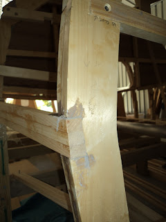
Below you can see how the right hand part of the frame was adjusted as the wood curves in on that side.
2. Once you have the first one on, I put the second and third on together and got them to line up with the first which was clamped in place separately as a guide.
3. Once all three are on, pull them all off and epoxy glue them on. I glued the first (bottom one) on by itself and then the top two together. Final adjustments with the use of many clamps, including making sure that all three lined up vertically and horizontally.
Below you can see the clamps holding the pieces together in each direction.
Once all the stringers are on it will still be necessary to taper part of it to match the change in hull curve. It is a bit hard to see, but the very top of the three stringers is a couple of mm outside the curve and will be sanded to match the curve above it shown by the frame. From the middle stringer piece to the bottom of the photo should be a straight line with no curve.
Some wider shots. All clamped on and glued:
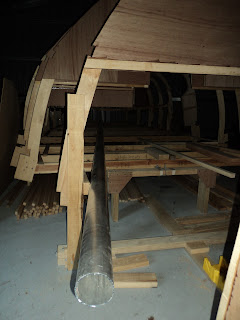
From the side:
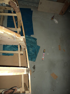
From above:
Finished with the ends trimmed:


