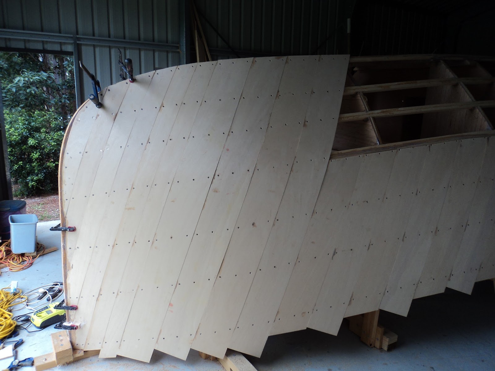
Had an extra day off and managed to get the full length pieces on the bow done over two days. Each plank is screwed the same as the others, but runs from the gunwale to the bottom of the hull.
Front prior to starting (this is an early shot without the flat bottom panels on):
First side commenced:
First side done from the front:
First side done, from the side before:
And after. Note the first four full 200mm wide planks heading forward, then I switched to 100mm wide for the rest they only got two screws per stringer. The thinner ones were easier to bend in as the bow is quite sharp from frame one to the stem.
Other side done, final look.
Thursday, 21 February 2013
Wednesday, 13 February 2013
Fitting a plank and first layer progress
For those who don't want the details of attaching planks, scroll down to the photos further down.
The process for placing a plank is fairly simple (the first one I just measured an angle around 20 degrees and clamped it in place, subsequent ones you butt up against the previous plank).
1) Place the plank in position and mark the line along the top of the chine stringer (the top as you look at it where the two chine curves meet), ensure you have enough sticking past the lowest stringer. Remove and cut.
2) Re position the plank and clamp in position at each stringer. You may need to cut or sand a bit off the edge where it meets the first plank to get it to sit against it. Don't worry about a small gap, epoxy from the second layer will be forced through to fill it.
3) Using a template (I made one from a scrap bit of ply with holes drilled in it) mark the positions for the three screws at each stringer, drill (don't go too far into the stringer or you will go all the way through) and then countersink the holes.
4) Put screws in the outside two holes (I left the middle one empty).
5) Remove clamps and repeat until you get to where you need to stop. I did eight planks in a day but for the last one have about 15 dry fit which will require a while to epoxy and clean up.
A single plank looks like this:
6) Remove the dry fit planks leaving the screws in place on the plank. I left the top one closest to the previous plank and outside one on the opposite side, next stringer down sticking out a bit to guide me/line up with the holes when I refit the plank to epoxy and screw back on.
7) Mix epoxy and glue powder, spread along each stringer using the holes from where you drilled to indicate how far, clamp plank back in position.
8) Screw on, I did all the ones beside the previous plank working top to bottom, then the middle ones and finally the last. My theory was the it will force the plank evenly on.
9) Remove clamps and move on to the next one.
10) IMPORTANT - once you have attached all the planks, crawl inside and scrape away the extra epoxy that will be running down from the stringer/inside of plank join. It is not much trouble, looks much neater and will be a thousand times easier than trying to sand it all off when the hull is flipped.
Where necessary I did leave a few clamps on to keep the bottom even.
The first side is planked all the way from the transom forward to just in front of frame 2 with epoxy and all screws in (see below photo). The next plank and all the ones forward from here will be full length hopefully on an even curve.
On the opposite side, from transom forward to frame six epoxied and screwed:
And from six to just forward of frame 2 dry fit:
From the inside, frame on the left is frame 6 (bookcase support):
And planks from frame 6 forward removed ready for final attachment:
Even though only dry fit on one side, couldn't resist an inside shot again to see how the hull is closing in the gaps:
The process for placing a plank is fairly simple (the first one I just measured an angle around 20 degrees and clamped it in place, subsequent ones you butt up against the previous plank).
1) Place the plank in position and mark the line along the top of the chine stringer (the top as you look at it where the two chine curves meet), ensure you have enough sticking past the lowest stringer. Remove and cut.
2) Re position the plank and clamp in position at each stringer. You may need to cut or sand a bit off the edge where it meets the first plank to get it to sit against it. Don't worry about a small gap, epoxy from the second layer will be forced through to fill it.
3) Using a template (I made one from a scrap bit of ply with holes drilled in it) mark the positions for the three screws at each stringer, drill (don't go too far into the stringer or you will go all the way through) and then countersink the holes.
4) Put screws in the outside two holes (I left the middle one empty).
5) Remove clamps and repeat until you get to where you need to stop. I did eight planks in a day but for the last one have about 15 dry fit which will require a while to epoxy and clean up.
A single plank looks like this:
6) Remove the dry fit planks leaving the screws in place on the plank. I left the top one closest to the previous plank and outside one on the opposite side, next stringer down sticking out a bit to guide me/line up with the holes when I refit the plank to epoxy and screw back on.
7) Mix epoxy and glue powder, spread along each stringer using the holes from where you drilled to indicate how far, clamp plank back in position.
8) Screw on, I did all the ones beside the previous plank working top to bottom, then the middle ones and finally the last. My theory was the it will force the plank evenly on.
9) Remove clamps and move on to the next one.
10) IMPORTANT - once you have attached all the planks, crawl inside and scrape away the extra epoxy that will be running down from the stringer/inside of plank join. It is not much trouble, looks much neater and will be a thousand times easier than trying to sand it all off when the hull is flipped.
Where necessary I did leave a few clamps on to keep the bottom even.
The first side is planked all the way from the transom forward to just in front of frame 2 with epoxy and all screws in (see below photo). The next plank and all the ones forward from here will be full length hopefully on an even curve.
On the opposite side, from transom forward to frame six epoxied and screwed:
And from six to just forward of frame 2 dry fit:
From the inside, frame on the left is frame 6 (bookcase support):
And planks from frame 6 forward removed ready for final attachment:
Even though only dry fit on one side, couldn't resist an inside shot again to see how the hull is closing in the gaps:
Thursday, 31 January 2013
The Hull is underway!
Got my 9mm ply delivered, mainly cut into 200mm wide planks with two sheets cut into 100mm wide for the bow where there is a sharp curve into the stem. Also got a supply of Phillips head stainless steel countersunk self tapping screws, 8 gauge x 5/8" to attach the planks.
Then there was no more procrastination, it was time to start. I had planed and sanded the frames stingers so was hoping the shape was not too bad. Time will tell.
Plank One. Each plank has three screws (countersunk) at each stringer position, the plank itself is on about a 20 degree angle. The planks are epoxy glued to the stringers only and not to each other. When you screw the second layer on at about 90 degrees to the first it forces glue into the joins between the planks.
I got two planks out of each 2400mm x 200mm piece of ply with a little bit left over. As you can see below I didn't bother cutting off the bottom, the building guild recommends at least 50mm past which I assume is to ensure full epoxy all the way past the stringer. After the two layers are on and the boat rolled over you trim it to the stringer. This is frame 8 to the transom which was a days activity.
The shot below is looking along the hull, and you can just see the shape/curve starting to show itself. Maybe you cant, but I got a bit excited anyway!
As you can see there is quite a way to got, don't expect the two layers to be done quickly.
Then there was no more procrastination, it was time to start. I had planed and sanded the frames stingers so was hoping the shape was not too bad. Time will tell.
Plank One. Each plank has three screws (countersunk) at each stringer position, the plank itself is on about a 20 degree angle. The planks are epoxy glued to the stringers only and not to each other. When you screw the second layer on at about 90 degrees to the first it forces glue into the joins between the planks.
I got two planks out of each 2400mm x 200mm piece of ply with a little bit left over. As you can see below I didn't bother cutting off the bottom, the building guild recommends at least 50mm past which I assume is to ensure full epoxy all the way past the stringer. After the two layers are on and the boat rolled over you trim it to the stringer. This is frame 8 to the transom which was a days activity.
The shot below is looking along the hull, and you can just see the shape/curve starting to show itself. Maybe you cant, but I got a bit excited anyway!
As you can see there is quite a way to got, don't expect the two layers to be done quickly.
Monday, 21 January 2013
Bottom layer done
I have been fairing the stringers in preparation for planking the hull. To get the top right you need to put the first layer of 9mm ply on the bottom as the sides overlap it.
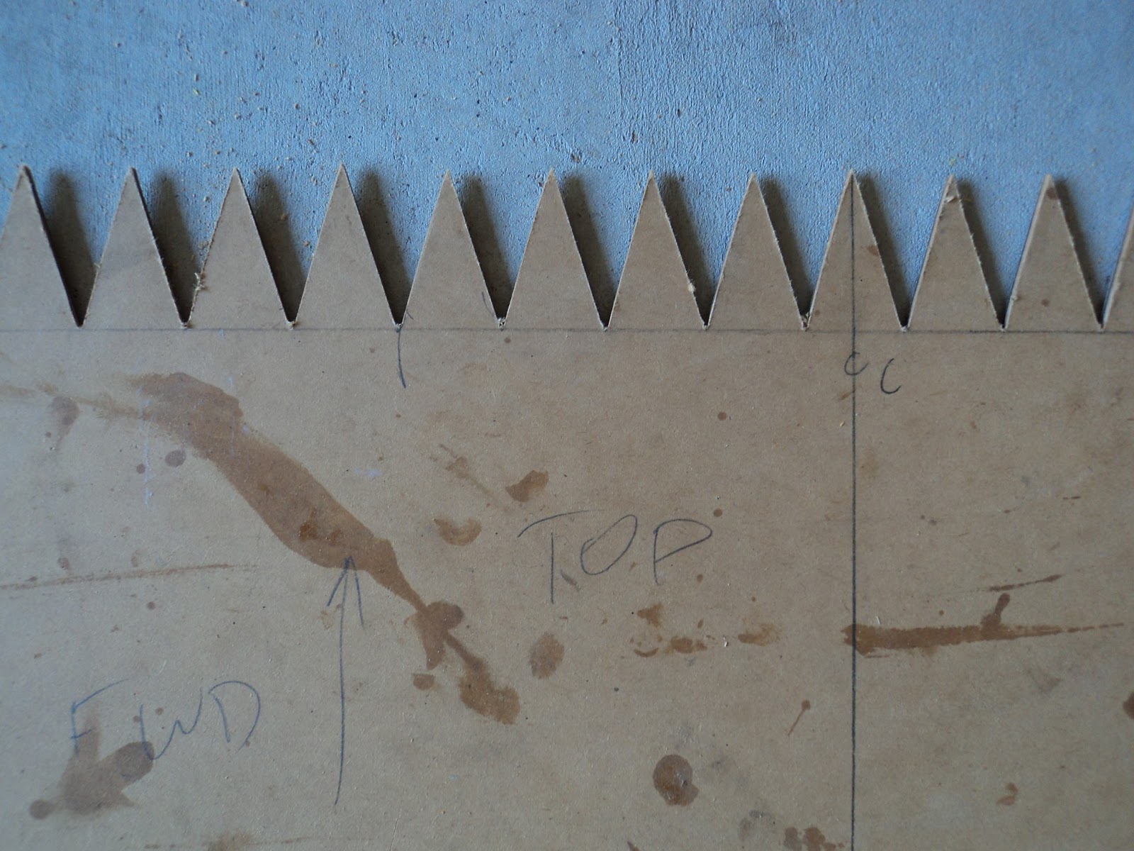
Instead of cutting a scarf along the face of each sheet and overlapping them, making a very long sheet that would be near impossible for me to position, the designer John Welsford uses a different type of join. The first step is to cut a zig zag pattern onto a template, each tooth 30mm wide and 50mm high.
Then you transfer this onto the ply. making sure that you offset the template on the second piece so they fit together. I did one end of each of the four pieces, and marked the others to suit when assembling.
Once I had cut the zigzag, I positioned the piece and marked the edges and holes for countersunk stainless steel screws then took it off and cut/drilled. Make sure you leave space on the centreline as there will be keel bolts coming through. Each piece is screwed on about 200mm spacing along the bottom stringer as well as across way into the hardwood cross pieces of each frame.
I started with a small section between frames 3 and 5 which was necessary to ensure I could use a full sheet across the floor of the 'cabin' without a visible join. Then I marked the front one out, sides and end and cut.
Then the main full length one followed by the one that meets the transom last.
A couple of inside shots which start to show how the hull is closing in:
Inside looking forward galley (fr 5 to fr 1)
The main cabin looking toward the cockpit. The middle bits of wood are a temporary support for frames 6 as there is no hardwood cross piece in the main cabin. The two small pieces parallel to the centreline are to support the sides and form the engine box.
And finally the cockpit to transom:
More fairing required and then order some ply for the hull.
Instead of cutting a scarf along the face of each sheet and overlapping them, making a very long sheet that would be near impossible for me to position, the designer John Welsford uses a different type of join. The first step is to cut a zig zag pattern onto a template, each tooth 30mm wide and 50mm high.
Then you transfer this onto the ply. making sure that you offset the template on the second piece so they fit together. I did one end of each of the four pieces, and marked the others to suit when assembling.
Once I had cut the zigzag, I positioned the piece and marked the edges and holes for countersunk stainless steel screws then took it off and cut/drilled. Make sure you leave space on the centreline as there will be keel bolts coming through. Each piece is screwed on about 200mm spacing along the bottom stringer as well as across way into the hardwood cross pieces of each frame.
I started with a small section between frames 3 and 5 which was necessary to ensure I could use a full sheet across the floor of the 'cabin' without a visible join. Then I marked the front one out, sides and end and cut.
Then the main full length one followed by the one that meets the transom last.
A couple of inside shots which start to show how the hull is closing in:
Inside looking forward galley (fr 5 to fr 1)
The main cabin looking toward the cockpit. The middle bits of wood are a temporary support for frames 6 as there is no hardwood cross piece in the main cabin. The two small pieces parallel to the centreline are to support the sides and form the engine box.
And finally the cockpit to transom:
More fairing required and then order some ply for the hull.
Thursday, 3 January 2013
Stringers done - Happy New Year!
With much patience from family (and doing a little bit at a time then waiting for epoxy to set overnight) I have finished all the stringers. Spent a bit of extra time hanging around and cleaning up each of the stringer/frames joints as much as I could removing excess epoxy.
On to photos, enough chat:
First three stringers done looking forward:
Looking overhead from the bow, three done on one side:
Looking overhead from transom forward (removed temporary wood between each frame):
Completed from the front:
From the side at the bow:
From the side looking back:
From the side at the transom:
Inside looking towards transom:
Inside looking forward, galley on left and over supports for berth to frame 1:
Started some clean up of the stringers and sanding the sharp edges off on the inside edge, leaving it square where it will meet the hull. Happy day.
On to photos, enough chat:
First three stringers done looking forward:
Looking overhead from the bow, three done on one side:
Looking overhead from transom forward (removed temporary wood between each frame):
Completed from the front:
From the side at the bow:
From the side looking back:
From the side at the transom:
Inside looking towards transom:
Inside looking forward, galley on left and over supports for berth to frame 1:
Started some clean up of the stringers and sanding the sharp edges off on the inside edge, leaving it square where it will meet the hull. Happy day.
Thursday, 13 December 2012
Stringers III - the inbetweeners
For those that came in late, each of the main stringers (I'll call them how I see them now on the building jig, top, middle and bottom) are made from three pieces of 20 mm x 25 mm clear hoop pine laminated together. This gives a final piece 60mm wide let into the frames a minimum of 25mm.
In between each of those goes two evenly spaced smaller stingers, two 20mm x 25mm so only 40mm wide. I scarf cut and joined wood to make the first four pieces that are full length. Then I had to mark out and cut the notches in each frame for them.
To do this I measured the distance between each of the main stringers and marked the frames. Then I got the straightest of the four and lay it along the frames so that it sat on each of the marks. A few minor adjustments and I could mark out the bottom of the notches. I used a metal rule to take the angle of the stringer looking from the side and marked a line on each frame, and carried it around onto the the fore and aft face of each frame. Then using the stringer as a guide measure the distance you need to let the stringer into the frame to maintain the curve and mark it. One side will be 25mm where the edge of the frame touches the stringer, the other will be more to allow the stringer to curve in.
Remove the stringer and use two pieces of the wood to mark the top lines, carry the lines around the side and mark the 'let in' measurement up and you have your notch marked. I used a hand saw cutting from the outside towards the centreline and followed the lines. It seemed to work okay, make sure you are checking each side of the frame as you cut as they are not the same depth front and back.
Now do this so you end up with 78 notches marked (don't count them until you have finished) all hand sawn to the correct depth and angle. I decided to mark and cut them all first before fitting any stringers, it just felt more efficient as I was into the swing of marking out.
Feel free to curse, particularly when you lean in to check a measurement and bang your head on the middle main stringer or crack your shins on the bottom one.
Using a chisel carefully take out the waste material working from each side. The cuts will prevent the frame wood splitting, and some will almost come out with a few hits from each side. You will be surprised how angled rear to front the final result is towards frames 1, 2 and 3.
Below is part way done, note the extra depth to be taken out on the forward side of the frames (up to 30-35mm in on the very front ones to allow the curve. If you look closely on frame two, three and four right hand side you will see that the notches are waiting for cutting, chisel work and finishing.
The below shot is a close up of the side to show hopefully the different depths:
And a final shot from the front:
Next update should show the inbetween stringers in place, things should move along a bit quicker but after the Christmas break.
In between each of those goes two evenly spaced smaller stingers, two 20mm x 25mm so only 40mm wide. I scarf cut and joined wood to make the first four pieces that are full length. Then I had to mark out and cut the notches in each frame for them.
To do this I measured the distance between each of the main stringers and marked the frames. Then I got the straightest of the four and lay it along the frames so that it sat on each of the marks. A few minor adjustments and I could mark out the bottom of the notches. I used a metal rule to take the angle of the stringer looking from the side and marked a line on each frame, and carried it around onto the the fore and aft face of each frame. Then using the stringer as a guide measure the distance you need to let the stringer into the frame to maintain the curve and mark it. One side will be 25mm where the edge of the frame touches the stringer, the other will be more to allow the stringer to curve in.
Remove the stringer and use two pieces of the wood to mark the top lines, carry the lines around the side and mark the 'let in' measurement up and you have your notch marked. I used a hand saw cutting from the outside towards the centreline and followed the lines. It seemed to work okay, make sure you are checking each side of the frame as you cut as they are not the same depth front and back.
Now do this so you end up with 78 notches marked (don't count them until you have finished) all hand sawn to the correct depth and angle. I decided to mark and cut them all first before fitting any stringers, it just felt more efficient as I was into the swing of marking out.
Feel free to curse, particularly when you lean in to check a measurement and bang your head on the middle main stringer or crack your shins on the bottom one.
Using a chisel carefully take out the waste material working from each side. The cuts will prevent the frame wood splitting, and some will almost come out with a few hits from each side. You will be surprised how angled rear to front the final result is towards frames 1, 2 and 3.
Below is part way done, note the extra depth to be taken out on the forward side of the frames (up to 30-35mm in on the very front ones to allow the curve. If you look closely on frame two, three and four right hand side you will see that the notches are waiting for cutting, chisel work and finishing.
The below shot is a close up of the side to show hopefully the different depths:
And a final shot from the front:
Next update should show the inbetween stringers in place, things should move along a bit quicker but after the Christmas break.
Saturday, 17 November 2012
Stringers continue
Slowly but surely moving along. I am only scarfing together long bits six at a time (three each side) as I move up and adjusting the notches takes a bit of time.
Finished the lowest ones (while upside down), someone pointed out it is the most important one as it defines the visible line of the edge of the deck. I should have started at the top (under water) then the middle and the most important one last as I got into it. I still have four each side between the main ones so too late now.
First one finished:
Middle one first piece:
Middle one side done, first on the other:
Below is the middle one finished, on the top left hand side the first one on the chine to bottom stringer is done.
Finished the lowest ones (while upside down), someone pointed out it is the most important one as it defines the visible line of the edge of the deck. I should have started at the top (under water) then the middle and the most important one last as I got into it. I still have four each side between the main ones so too late now.
First one finished:
Middle one first piece:
Middle one side done, first on the other:
Subscribe to:
Posts (Atom)