Monday, 4 February 2019

Rub rails, taff rail, main hatch and lifelines completed

The momentum towards completion continues, with what I think is a large visual change externally.  Once the taff rail was built I took it off and down onto the shed floor for final sanding, and then paint.  With the paint brush out I took the opportunity to pull out other final paint items.

First up was the main hatch which got two thick coats of epoxy wet on wet for sealing. 


Followed by a sand and two coats of oil based sealer undercoat:


Then it got several coats of water based house paint.  At the same time I finished the main hatch entrance which had a piece of hardwood screwed and epoxied onto the inside on both sides:


This also forms the drain for the edge of the main hatch, sloping aft towards the cockpit to drain down beside the washboards.  This is from above, aft to the bottom of the page.


After a sand they got painted as well as the rails:


Then the whole lot was put in place and the garage screwed on.  Note the handrails on the outside, I didn't want to put holes in the cabin roof, and it also leaves the sides of the cabin clear for sheets it I decide to run them aft.


Around paint drying I final mounted the nav lights on the bow (just aft of the first stanchion), along with fairleads (just above the end of the rubbing strake) and the whisker stay plates each side (in front of the nav lighst).


This then led onto mounting the padeye for the attachment of the forward end of the lifelines, using some nylon rope to check the runs.  I was going to put it forward of the fairlead, but the lifeline would foul forward mooring lines:


I also cleaned up the brackets my father welded up in stainless to strengthen the forward end of the taff rail (more later in this post).  The hole allows a coach screw to come up from underneath through the end of the combing, the upright plate stops the wooden post being dragged forward by the lifelines and the piece leaning against it  gets through bolted between the post.  Vertical plate down the outside of the combing gets two countersunk 8g 25mm screws.


Today's (9 Feb) working bee was to mount the taff rail, finish sealing the rubbing strakes while we had the sika marine sealant out and then mount the lifelines.  We tape up around the quarter deck, rubbing strakes where we needed to and spread sika everywhere, sometimes even where we needed it.  Below shows the taff rail bolted screwed and stuck in place.


And a shot showing the bracket.  The two through bolts are 6mm stainless:


And from the side showing the rear plate spreading the load of the bolts.  Originally we only had the bolt from underneath the combing, this is much stronger.  The tape was for the continuation of sealing once we had the taff rail on.


After sealing the final bits of the rubbing strakes we ran the lifelines down each side.  5mm galvanised wire with allegedly sun resistant plastic PVC coating.  Swages each end, the aft fitting that goes through the wooden post is threaded which allows some ability to tighten but they are not structural so no point overdoing the tension.  Below is looking aft from the main cabin hatch:


Looking from the corner of the shed down the port side:


Looking across the transom, didn't end up buying the winches yet but took some measurements and hopefully the handle with turn between the lifelines (or my measurements are out, which is a good possibility!).


Looking aft along the deck from the anchor well:


And forward from the quarterdeck:


Only mishap was I forgot to feed the final lifeline back through the stanchion after I cut it to length before Dad and I put on the swage.  Extra trip to the hardware store to replace it (replaced and shortened the first one we did seeing we had a two pack of swages) but only lost an hour.


Externally I need to paint the outside of the washboards and then I can think about pulling it out of the shed perhaps.  Need to ring the engine bloke again, he is flat out but has most of the fittings etc ready to go.

Inside I have started cutting the foam matresses to fit, first one is away with mum while she looks at covering it for me.  Also have the extra ply to build the engine box/step/table.  Then splash around some paint in the main cabin and start ringing riggers/boat transporters and sailmakers.  That will take longer than I think as usual.....


Sunday, 20 January 2019

Rudder, rubbing strakes and taff rail continues

The taff rail continues fabrication.  Below shows it sitting in position after sanding.  The forward uprights are still to be cut to length, but my father has fabricated two stainless steel fittings to go underneath them to strengthen the attachment to the coaming.  They will be shown when mounted, but will be through bolted to the upright, and will be screwed in two directions onto the combing (along with the original coach screw).  I am thinking I will need to buy the winches to check lifeline interference with the handles to determine final height of the forwards bits.


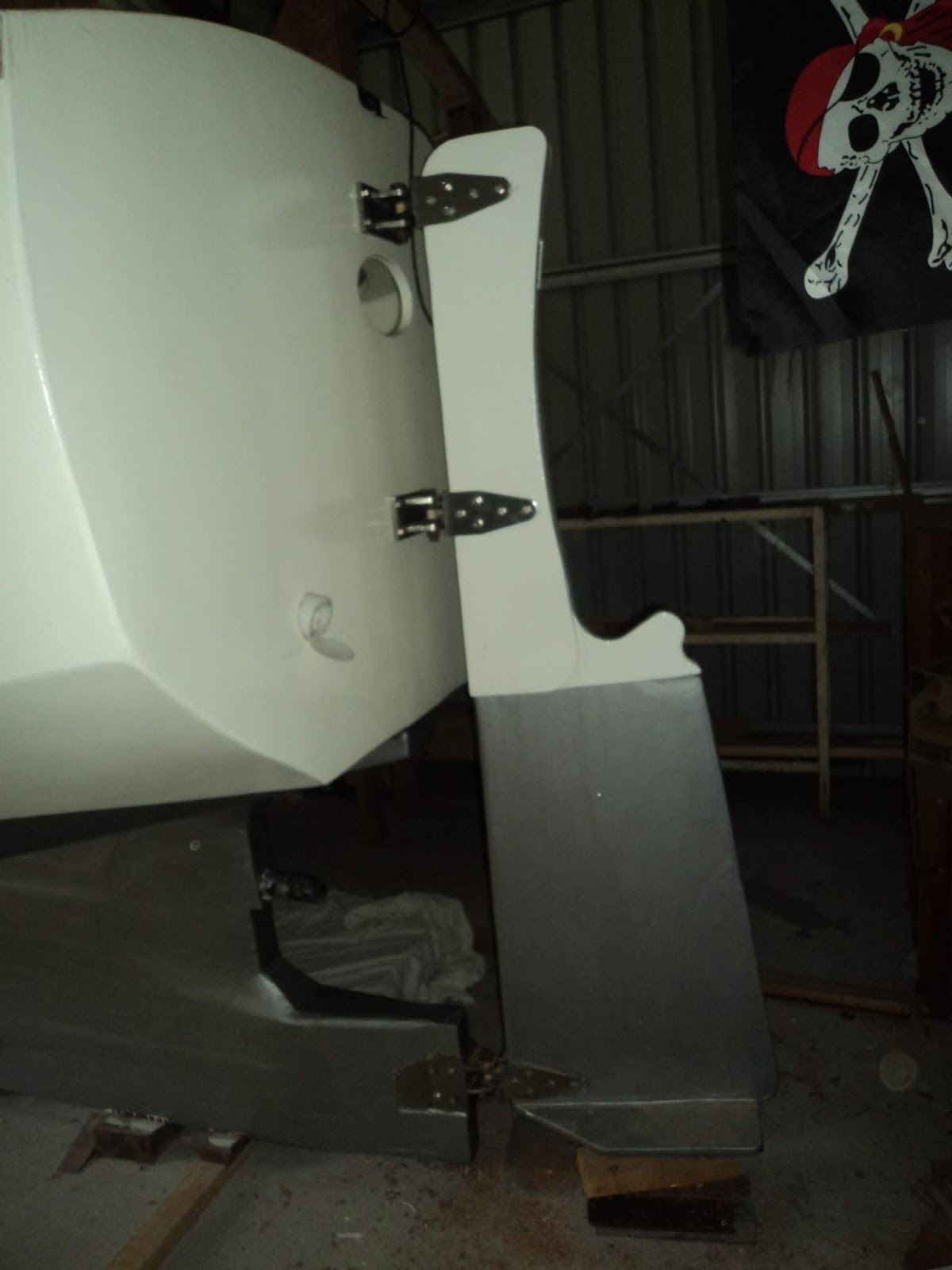
One of the other tasks was to mount the rudder.  I had already fitted the top transom fitting, so we could block up the rudder to determine final bottom fitting position.  Then it was on to fitting the middle one which has a 20mm hardwood backing plate inside the transom in the rear storage area, see below (excuse the flag, my son found it somewhere...).


And a close up of the top two fittings and the hole for the tiller looking into the cockpit.


And all done.


Final task of the working bee was mounting the rubbing strakes onto both sides of the hull with sika marine sealant and silicon bronze 14G 5-mm (two inch) screws 250mm apart.  Below is putting on the sealant after taping up around where the wood will be:


There were three of us initially, and then mum had to help as well to hold the top one when we started at the stem because of the length and curve.  After peeling off the tape quickly I then sanded them all, and have filled a few screw holes left from laminating the third layer on where the chainplates will go and elsewhere.  Paint with epoxy sealer undercoat and then topcoat to follow is my goal for the next week.


And a final shot from a distance, very hard to get a good shot that shows the whole boat.


No photo but all the electrics are now completed, with the interior lighting and fans operational. Of he nine lights only two didn't work first time, one the plugs were reversed and the other was a thin wire I had broken when crimping on a component but easily fixed.  One of the two forward berth fans had a similar crimping/broken wire issue so fairly happy with that outcome.

Work continues, with motivation high.


Saturday, 5 January 2019

Welcome to 2019 - Launch Year (I hope)

Nothing like putting an end date to focus your attention.  My original plan was a sedate 10 year build, allowing family responsibilities to reduce and leave me some time to build sailing skills around work.  I built the first frame around May 2012, and had a 16-18mth break from building when work travel increased for a while.  So 2019 it is, say seven and a half years in the shed if I can make it by the end of this year.  We will see how it goes, but I've put it up as a target.  It was never a rush, and am glad to have taken my time.

Christmas and New Year did not see much movement in the shed, but a few things are underway.

Rudder Fittings:
I got three silicon bronze bolts with castle nuts, 16mm diameter and 90mm long which go through a nylon bushing (see below):


And from the side close up:


One fitting is already on the transom, need to fit the bottom fitting the keel and hang the rudder.  This will allow positioning of the middle one correctly.  Two of the three are drilled for a pin to lock the bolt in place already (little Christmas project at my fathers one morning), with the third to be done when fitting the rudder as the fitting was already on the boat and didn't want to drill it without checking.


Rear quarterdeck railing:
The other progress is the rear railing.  My original prototype was based on the same height above the rear quarter deck as the lifelines are on the side deck (below from a previous post).


I was a bit concerned about strength after I notched the hardwood rails into the posts, and similar concerns were expressed by people on the woodenboat forum which confirmed my own worries.  But one suggestion was to have no railing at all.  When standing on the cockpit floor the rear quarterdeck is mid torso height, but the space between the end of the cockpit seatback/coaming and the rear samson posts worried me.  Another of the forum members suggested a small taff rail (don't ask me, I don't make these names up!) and posted the below photo (from channelcutteryachts.com).


I liked the idea of a low rail, with large supports but would have a narrower handrail.  I dragged out the last kwila keel sleeper I had left, 150mm x 75mm thick and did some brainstorming.  Rail would be laminated in place from hardwood, with the curve matching the quarterdeck.  Three layers of 65mm x 12mm Tasmanian hardwood (ending up 36mm or 1 1/2 inch thick), which follows the side deck forward to the rear of the combings as I originally planned with the thin hardwood earlier prototype.

Below is the first support in the middle of the quarterdeck, which was adjusted on the base so it was level in each direction, and on top.  It is mounted through the quarterdeck, and a hardwood 20mm thick kingplank underneath with 2 x 140mm x 10mm galvanised coach screws.


Each of the side ones were made vertical and level, which took a lot more effort and again coach bolted, but through the quarter deck only (but they are beside the forward rail which braces them).  Below is one of the side ones about to be trimmed and sanded, lower one is the middle one shown above).


And sitting in place:


Then I epoxied on the first layer of hardwood, pulling it down with ratchet straps and a countersunk 14g x 50mm screw down into each hardwood support to hold it while the epoxy set.  Thick fillets each side of the support posts to strengthen the post to rail joins.


The forward posts on the end of the combing are 70mm x 50mm hardwood, which I left over length.  The side rails are notched into the posts and epoxied.  Below shows the forward posts with tarps down for epoxy.


Each layer at the join between the side and aft rails alternates at the join for strength, below are all the pieces ready for epoxy this morning.


And after some ladder climbing with slippery pieces, in place from the side, you can see the alternating wood left over length for trimming once the epoxy is dry:


And from the cockpit looking aft, as close to the middle as I could get.


And a shot of the starboard side of the transom:


The rail is about 26cm above the deck edge on the quarterdeck and sides, which should match the height of the lower side deck lifeline.  I am going to use the posts on the coaming to attach the aft end of the lifeline fittings, and will adjust the top of the post down the track.

Next up is to trim, sand and finish the railing, prior to painting and sealing to the deck.  They will be sealed at the same time as the rubbing strakes go on, which is hopefully during a two day working bee in the next week with a few helpers coming over.

I'll take some photos when it is cleaned up, but I am happy with the strength, height and look so far.


Mal


Saturday, 10 November 2018

Mast assembly

Years ago, yes it has been that long, part of my initial construction was the mast pieces.  I say pieces because I cheated, I couldn't see me being able to  make a round mast by laminating wood and shaping it.

So I followed the building guide's other suggestion, which was to substitute the middle section with a marine alloy tube.  Mine is 6.5m long, 100mm in diameter and a couple of mm thick.  It weighs about 16kg from memory and easy to carry.  The top and bottom sections have solid wood pieces that are a tight fit to slide in, through bolted once the tube is in place.  The whole completed mast is 9.8m long, and too long to fit neatly into the shed.

Below is the bottom wooden section of the mast.  The silver bit half way up is the pivot pin which is stainless steel and fits in the tabernacle.  The base piece is hollow for a small section between the base and the solid bit for the pin, and between the pin and the top.  The bit that sticks up is solid wood and continues below the platform the same distance it goes above it for strength.


This is a close up of the platform for the boom jaws to pivot on, the hardwood supports it rests on and the space inside where the alloy tube slides down.  The hole is one of two drilled through for 6mm stainless steel bolts.  The bolts overlap in an X 10-15mm apart for strength.


This is the top section, the edge you can see on the left is the forward one, on top is a platform with the tri-colour/anchor light and behind it a wind vane.


When I made the top section, which is partly hollow and solid where the rigging fittings will go, I cut the inside filler wood with an angle on top and a hollow down one side.  This was to allow any water that got in to drain down and out of the mast, and to also allow me to run wires for the top light.  I left a piece of wire inside when I constructed it to pull the wires through.

After some swearing and several attempts I managed to get five strand 12 volt trailer wire through.  This allows extra wires for down the track if I need them.  Below you can see the wire before I attached the top to the alloy tube.


And this is with the alloy tube attached.  Because of the wires I couldn't alternate the direction of the bolts.  I'll talk to the rigger down the track and strap it if necessary to re-enforce it.


The tube attached to the bottom section:


And a close up of the bolts.


We are now almost up to date.  I have cut a slot in the bowsprit and fitted it over the stem fitting with the aft end bolted and supported into the fitting in the anchor well.  Photos to follow.

2019 will be launch year, I am running out of jobs that I will do myself.............

Scary.

Aug/Sept update Underwater Seal and paint

I've been slowly working along, not often with lots to show for it.  With the non-slip in place I drilled holes through the deck and hardwood pads for the stanchion bases.  Due to the angle of the bases the inboard two holes are through bolted with 6mm stainless bolts, the hull side two holes are two inch 14G stainless steel screws. 


I have also permanently mounted the portholes on each side.  Unfortunately the inside surrounds did not fit properly as they came in two halves and because of the thickness of the cabin side left a gap when positioned.  I ended up getting six 3mm thick aluminium rings CNC cut for just over $100 and drilled them myself to fit which worked out fine. 


Below you can see the port side stanchion and bases in place (see below for the silver underwater seal).


As I was doing this I was running electrical cables inside and attaching fans, charging points and lights.  The under waterline seal consisted of epoxy sealer/undercoat first (several coats), the same as above the waterline.


And aft:


This was followed by International Primocon (numerous coats).  This is in place of the topside paint and is aluminium based I believe and compatible with anti foul paint that will be applied just before launch:


And aft:


I've added the top rudder support, and attached the exhaust transom fitting along with the scupper covers for the cockpit drains.  You can see the four holes for the fitting just above the hole in the transom for the tiller.


The last part of September was starting on the rubbing strakes.  I laminated these from one layer of 10mm pine and one layer of hardwood, top ones are 70mm wide and the lower ones 40mm.  I put a third layer of 10mm hardwood where the chain plates will go to allow for adjustment to make them sit against the hull.

Below is the port side lower one epoxied and screwed in place drying with tape underneath to prevent it sticking to the hull.  You can see the third layer comes aft to halfway down the cabin, the clamps are helping keep them all aligned.


Jumping forward a bit here are the two port ones off with sealer/undercoat on the inside.  Right one is the longer deck edge one, more on the mast next.


Next post mast work.