Thursday 10 October 2019

Electronics and little bits I missed along the way

With the boat out of the shed I could continue on with preparation for launch.

I started making a box to put on the rear of the cabin to hold the Raymarine Chart plotter (Element 7S) and the radio (Standard Horizon GX1300E).  I was originally going to mount the plotter on some form of swivel so I could move it around into the companionway to see it from the cockpit.  But modern technology overtook me.  The chart plotter can connect to a phone or tablet, both of which I have already, so a permanent mount inside was the go.

Below is the front cover started looking from the inside out.  The bit missing is a ply rear solid piece which was epoxied and screwed into the rear cabin wall (12mm ply).


This is the front which is removable.  The bottom middle piece ended up being removed to allow space for the plotter.


This is the permanently mounted section of the  box.  The top and left hand side are glued and screwed to the rear ply (which is onto the wall before painting).  The radio mount is on the right.  Wires being run through, I also had to run the radio cable (cockpit rear handrail) and transducer (rear of transom) forward.  This was done with through deck fittings to keep out the water, and the wires running under the cockpit seat on the starboard side forward into the foot of the berth, then up into the storage area behind the cockpit seats (long items storage each side back to transom).  The opening to that area is the square just below the wall unit.


And a final view.  The radio is recessed through the end piece, and the bottom piece slots on and is held by two screws.  I drilled air holes under each for ventilation, I will see if I need more.


The linking of the plotter to the radio was not as easy as I first thought, being different signals (NMEA2000 vs NMEA0183).  I wanted the lat and long displayed on the front of the radio as well for calling in an emergency, so needed a Raymarine converter unit and another cable to get them to talk to each other.  Worked out okay, I mounted it in the long storage area where I had to roll up all the extra wire from the radio and transducer, as they cannot be cut to length.


With Dad back to help (again, he had been down to put a stainless plate on the cockpit rail for the radio aerial) we attacked the mast tabernacle.  It sits in a space at the front of the cabin and is constructed from 6mm steel.  Underneath it is a 20mm hardwood pad, then the deck (fibreglass over two layers of ply, then another 20mm hardwood king plank which is supported by several curved deck beams and finally a hardwood compression post.

Below is with it bolted in place, you can just make out the bottom of the radio aerial on the top left.  Wire sticking out is the connection to the wire for the masthead/nav lights inside the mast.


The tabernacle was bedded on butyl rubber, with the bolts being 8mm stainless.  Below shows the starboard side, rear two bolts onto a single 6mm steel plate with spring washers, and the forward one onto a 40mm square 6mm plate with spring washer as it goes all the way through the curved deck beam as well.  It's handy having a fabricator to call on!


This is the port side inside the galley space.  Disregard the bolt to the right, is is reinforcing for the rear curved deck beam.  The forward two are the two rear tabernacle bolts, with washers and spring washers against the 20mm hardwood king plank.  The vertical piece of wood to the left is the kwila hardwood compression post.  The front tabernacle hole has a 110mm x 8mm stainless coach screw that goes down into it.


Seeing we had the mast, we threw it up for a test to see how it looks.  Bit of safety tape for a flag.


I have also finalised the under galley area.  In the untidy photo below you can see the main galley with a gimbled spirit stove, and to the left there is a sink with drain tray.  Directly below the stove is a pull out draw for storage or knives, forks, cooking stuff etc.  At the very bottom is the access to the underneath storage.


I am not permanently putting in water tanks or a grey/black water system.  To the right out of shot is an access door through which the cassette for the toilet can be removed.  Further-est from shot is a 10 litre water tank connected via hose to a hand pump on the galley bench over the sink.  The closer 10 litre will be waste, although I intend washing most dishes in a container in the cockpit where I can throw the water overboard.


This shows how the water container can be easily removed for top up.  The white hose to the left has a normal hose joiner clamped in it (it has an o ring as well, and I had to heat up the tube to get it in so tight fit).  The black attachment is an adapter from a normal hose to a 13mm watering system, again clamped into the hose after heating.  The hose continues down to the bottom of the water, and there is a fitting and rubber seal to stop water splashing out hopefully with motion of the boat.

The black waste hose on the left is a slide in tight fit to the container.


That is the low tech version of how I will start.  We'll see how it goes but little to go wrong.

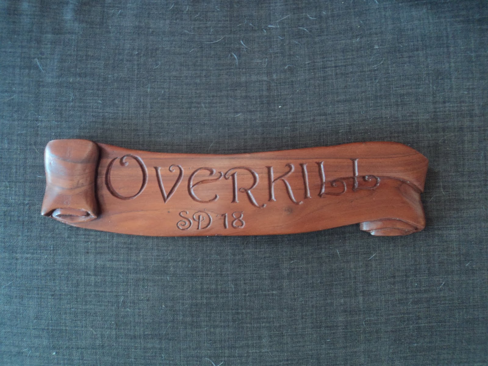
And finally a gift.  One of the contributors on the Woodenboat forum was away from home and filling his time with some carving.  This will grace the inside of the access hatch into the cabin.  Photo to follow when mounted after some prep/painting/finish of the entry.  It is about 600mm x 150mm carved scroll with the boat name and sail number in hardwood.  Looks fantastic.


A big clean up is underway inside the boat, refitting a few doors in the main cabin and a little bit of paint and then I think it is time for the berth cushions to be put in.


Mal

Friday 13 September 2019

Electrical gauges and out of the shed

I didn't take a photo earlier but this is what the electrical system fit out looks like now.  Below is from the forward side of the cabin looking aft.


And a close up.  Battery selector top right with isolation switch below it.  And the board to select circuits.  Still have to paint the floor after the engine install.


Other progress is we took a few deep breaths and decided to roll it out of the shed.  First off was to double strap down onto the cradle to reduce rocking.


Then it was time to jack up and put rollers under the cradle.


Yep, still surprises me we can roll this thing out on 10mm steel rods.....


Then we were ready to winch, strap onto the cradle and cable run out.


Below we are underway, about half way to the cradle being off the slab.


And a shot from inside:


Plenty of clearance on the 3 metre wide opening of the shed.  There was a little bit more on the other side, about 4 fingers width!


Almost there, about to drop the rear of the cradle off the concrete slab onto hardwood blocks.  We had to keep jacking it up to put new rollers in under the front as they went out the back of the cradle.


And success!  Light fading as I enjoyed a Corona and admired the lines from various angles.


Since then I have attached the bowsprit, still waiting on a through bolt in stainless through the top of the stem fitting.  It is bolted into a socket in the anchor well, with another piece of hardwood wedged underneath it with two bolts through it to prevent the bowsprit moving up or down.  The orange bit is a piece of plastic so no-one drives under it in a truck and snaps it off!


Below is a shot down the bowsprit showing the support for the stainless steel anchor roller, along with hardwood for the chain to run down.  I have a 16kg anchor to go in.


And a shot showing the socket middle top of photo where the bowsprit is attached and bolted.  The chain run is hardwood lined with cut up cheap kitchen cutting boards.  Once they wear I can easily unscrew them and replace for less than $10.


Next on the list is completing the mounting box and running lines for the radio and chart plotter/depth sounder inside the rear of the main cabin, and completing the painting in there.


Then:
- rigging
- sails
- engine connection
- transport and launch

But a major step being out of the shed.


Mal

Tuesday 13 August 2019

Prep to move out of the shed and name/rego added

I still had a few things to finish while the boat was on a secure concrete footing to allow for winching it out of the shed.

First off was the boat cradle.  Many moons ago we had to cut the building cradle cross pieces to slide in the lead keel. Since that time I have had long pieces of wood screwed and clamped together to hold the two halves in place. 

Below is November 13 (wow, time flies) showing the building cradle:


And April 15 with the keel in place, the wood to the left once went all the way through forward and aft.


To reattach the two we had to again get the jacks and blocking out, and raise the entire boat front and rear until we could slide in pieces to cover the gaps across.  We used the same dimension structural timber, longer than the gap with extra wood each side of the cut to continue underneath the upright supports.  These were then bolted through with two or three 10mm galvanised bolts each side, with extra hardwood bolted on the other side in the gap to strengthen against flex.  We also had to remove the upright supports against the chine of the hull as these were outside the width and wouldn't fit through the shed door.

We then jacked the whole thing up higher again, and put hardwood pieces 75mm square (the last of the kwila keel timbers cut in half) parallel to the keel and just outside.  I have another piece to put directly under the keel, but it is not in place yet which will be covered shortly.


This is a shot from front on, showing how I had to limit the width to get out the door.  The two hardwood slides are under the inner most upright support each side, the final one will be directly under the keel.  I have added straps from the chainplates to the support to reduce movement side to side but seems as secure as it has always been.


With the extra height I could then epoxy over the final rear keel bolts with sanding filling powder mixed in.  Previously these were too close to the floor to get at, and once set they were sanded to match the keel. 

The final prep is to paint the underside of the lead and the rear hardwood sections of the keel which I could not get to.  So far I have done two coats with International Interprotect epoxy sealer/primer but need to get some more.  Below is looking aft from the rear of the lead keel towards the rudder:


For sometime I have been getting asked what the boat name will be.  A bloke I know who is doing up a runabout let me know that the Queensland Department of Transport now allows you to pick your boat registration number, and you can reserve one free of charge for six months before launch.  A quick check revealed the boat rego I wanted was free.  Down I went to sit around for 45minutes waiting and it was mine!  The boat will be Welsford Sundowner sail number 18, so the boat registration number will be SUN18Q.

Now the name.  

During construction on a number of occasions one term kept cropping up.  Be it when I told people I was going to build a boat in the shed, the size of the keel we melted, the thickness of the rudder pintles or just in general conversation.

'Overkill'.  eg "how big is it going to be?  That's a bit of overkill don't you think".  Dictionary.com had a definition that also struck a chord as well.

overkill [oh-ver-kil]

noun

- the capacity of a nation to destroy, by nuclear weapons, more of an enemy than would be necessary for a military victory.
- an instance of such destruction.
- an excess of what is required or suitable, as because of zeal or misjudgment.


Sounded like me.  It is also the title of one of my favourite 'Men at Work' songs.


So that was the name sorted.

I started looking at boat names and rego stickers.  After looking around I bought some from Boat Names Australia (www.boatnames.com.au) and they were sent out in the post.  A couple of viewings of the youtube videos on how to stick them on and away I went.  I have no connection to them, but they were a good price, had an online design tool you could use to check fonts, were prompt and looked like I could apply them.

Process was easy: clean the hull with metho, position the name, peel off half the backing, spray soapy water on and attach using a provided tool to press on, do the other half and leave it.  Come back in half an hour and wet down with water, leave for 30 seconds then carefully peel of the front cover. Below shows the registration number and home port ready to be fixed on the port side of the transom:


And the name on the starboard side:


The transom is too close to the back of the shed to line up the camera so the photo is not level, but I used one to line up the names etc so they should be.


After looking across the transom:


And again the photo looking straight at the transom is not level, but you get the idea:


I will continue to paint the underside of the keel, then it is time to drag the boat out of the shed to mount the mast tabernacle (would make it too high to get out of the shed if done inside) and organise the engine mounting and truck.


Mal

Saturday 6 July 2019

Quarterly Update - Chain plates done, internal cushions and anchor roller mount

House renovations continue to compete with the important part of life in the shed, along with totally destroying the boat fund but I continue on.

Last instalment I was working on the chain plates and positioning them.  I had just finished cutting them out.  Below shows the kwila external ones notched for the chain plates and the internal ones which are two layers of 12mm hardwood glued together.  On the left bottom you can see the 6mm stainless steel backing plate for the inside.


Once they were all shaped I marked them with a chisel and painted them all with sealer undercoat and then a couple of coats of exterior paint.  Below is the grey sealer undercoat (two coats).


These are the tools I used to drill the holes for the chain plates (mostly successfully).  I started with a smaller drill using squares and level to attempt to get them straight.  I drilled the top forward and very bottom holes of a chain plate first, as deep as the drill bit would go followed by a smaller hole with the brace and bit.  Once I cut through inside I could drill (it was only a small distance at the top and bottom where it hit inside stingers) and position temporary threaded rod.


Once the top and bottom threaded rod were in I could position the external chain plate and the internal backing plate.  Then the procedure was the same, with the small electric drill bit and brace and bit hole allowing me to see where I was going.  If I was off, it was easier to adjust my drill angle from outside when I went to the final hole size to hit the backing plate.

Below shows the port side middle chain  plate, which is the galley inside, with temporary threaded rod.


And from the inside.  The top bolt (forward side), goes through the gunwale stringer and the bottom bolt through a lower stringer, the others just the hull.  The hardwood backing plate goes against the ply hull and packs out the gap so it can be bolted in place.  The aft top hole on the middle chain plate each side got a stainless coach screw.  All others are total through bolts.


Below shows the holes you end up with in the hardwood backing plate and the hull/rubbing strakes.


Once I had drilled all the holes I measured and ordered all the bolts in stainless steel, bought some more tubes of sika marine sealant and called on my father.  Together we liberally spread sika between the hull and the backing plates and into each hole, and bolted down the plates.  I chose not to sika the inside, if I see water that means I need to give them attention rather than have water between the outside and inside sitting.

Below shows the final view of the port side chain plates.


I have also finished painting the engine box which is below.  At the front is a slide in cover which may have an air vent (to be determined) and a slide on top which will form my table and also the step to get up into the cockpit from the cabin.  The entire thing attaches to the engine bay with a few screws and can be totally slid off into the cabin space towards the galley for all round engine access for servicing.


Another exciting task was cutting the foam for the berth cushions/seats.  Below shows the complex angles with the curve of the hull to the left, the top surface fitting around a frame and then joining another.  This was before I painted the ply seat tops, from memory the foam is 150mm thick.


Below shows the port side forward one closest to the galley.  The fridge wiring runs to here as well, so I may make another smaller one which can be swapped in.


Below is a view looking forward in the forward cabin.


And a shot looking aft.  The main mattress is split to match the swing up supports underneath.


Below are all the finished cut foam pieces before I sent them off to the seamstress (my mother) for covering.  She has threatened me with bodily injury if I ever ask her to do anything similar again.  The angles, cut outs and curves were a nightmare.


A bloke I work with who helped me connect up the 12v wiring also does a bit of 3D printing so made up a mount for two gauges for the house battery/current draw and cranking battery.  I had to cut the top name plate part off to fit it where I wanted, but mounting is underway to allow me to monitor the power.


My final project has been an anchor mount.  I have purchased a mount and a 16kg anchor, but figuring out where to put the mounts with all the bowsprit rigging was a challenge.  I didn't want to drill holes in the bowsprit, so have used some of the kwila (100mm x 100mm) from the renovations and also some off cut hardwood to make supports front and rear that clamp onto the bowsprit with 10mm gal bolts (solid pieces right and middle in the photo below).  These support the fitting at the left of the photo which is an angled piece of 20mm hardwood (with 20mm doubler underneath) which has 19mm hardwood sides to keep the chain/anchor contained.  The fitting is angled down slightly, which was a challenge when the bowsprit angles up 12 degrees.  I have now painted it and lined the anchor support with sections of polyurethane cutting board but the photos had too much sun on them to be useful.  I will take some more.


That about gets you up to date.  Plan now is to finish mounting the battery gauges, keep working on a plotter placement bracket and drag the boat out of the shed pending engine connection.

Quotes for sails have been obtained, still chasing riggers.