Saturday 10 November 2018

Mast assembly

Years ago, yes it has been that long, part of my initial construction was the mast pieces.  I say pieces because I cheated, I couldn't see me being able to  make a round mast by laminating wood and shaping it.

So I followed the building guide's other suggestion, which was to substitute the middle section with a marine alloy tube.  Mine is 6.5m long, 100mm in diameter and a couple of mm thick.  It weighs about 16kg from memory and easy to carry.  The top and bottom sections have solid wood pieces that are a tight fit to slide in, through bolted once the tube is in place.  The whole completed mast is 9.8m long, and too long to fit neatly into the shed.

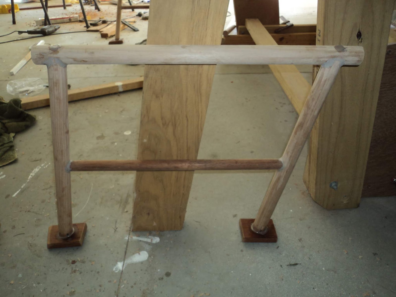
Below is the bottom wooden section of the mast.  The silver bit half way up is the pivot pin which is stainless steel and fits in the tabernacle.  The base piece is hollow for a small section between the base and the solid bit for the pin, and between the pin and the top.  The bit that sticks up is solid wood and continues below the platform the same distance it goes above it for strength.


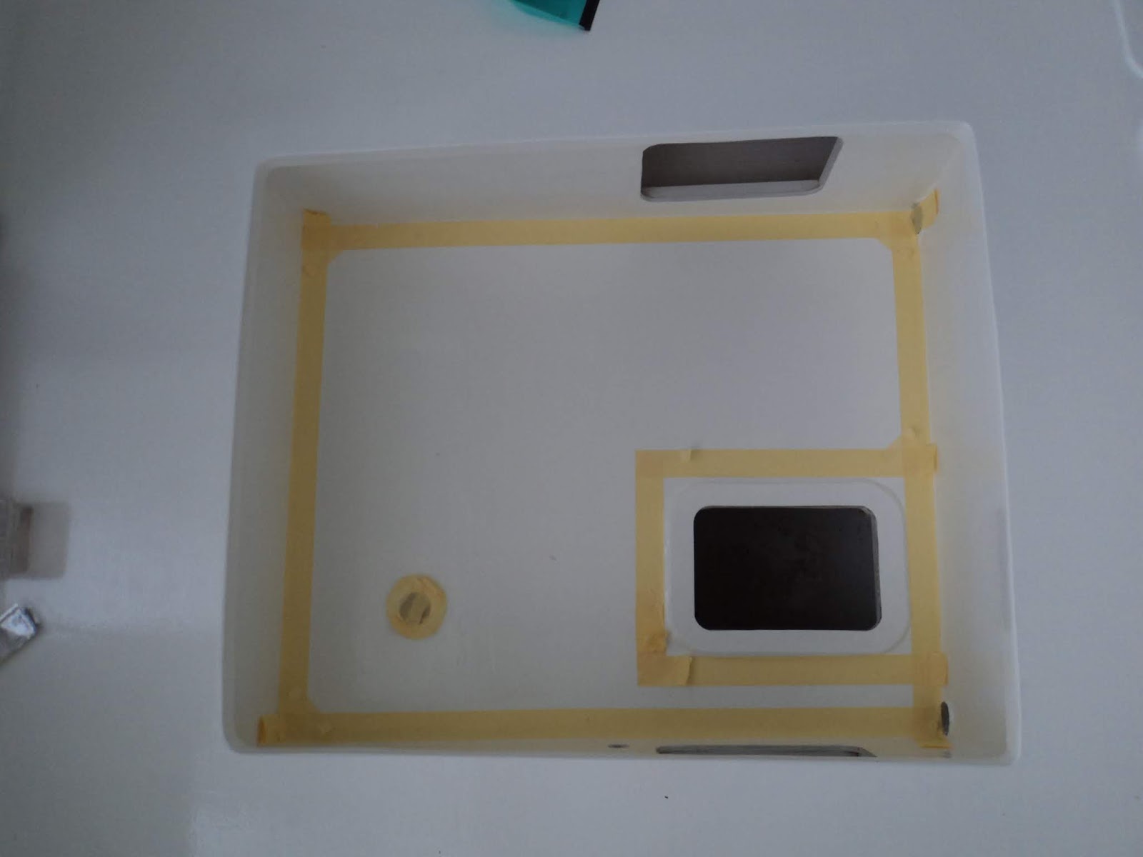
This is a close up of the platform for the boom jaws to pivot on, the hardwood supports it rests on and the space inside where the alloy tube slides down.  The hole is one of two drilled through for 6mm stainless steel bolts.  The bolts overlap in an X 10-15mm apart for strength.


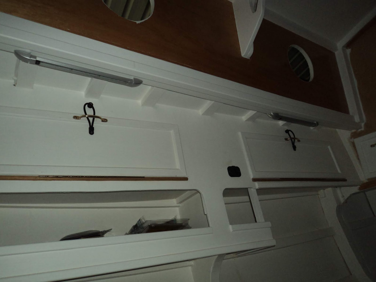
This is the top section, the edge you can see on the left is the forward one, on top is a platform with the tri-colour/anchor light and behind it a wind vane.


When I made the top section, which is partly hollow and solid where the rigging fittings will go, I cut the inside filler wood with an angle on top and a hollow down one side.  This was to allow any water that got in to drain down and out of the mast, and to also allow me to run wires for the top light.  I left a piece of wire inside when I constructed it to pull the wires through.

After some swearing and several attempts I managed to get five strand 12 volt trailer wire through.  This allows extra wires for down the track if I need them.  Below you can see the wire before I attached the top to the alloy tube.


And this is with the alloy tube attached.  Because of the wires I couldn't alternate the direction of the bolts.  I'll talk to the rigger down the track and strap it if necessary to re-enforce it.


The tube attached to the bottom section:


And a close up of the bolts.


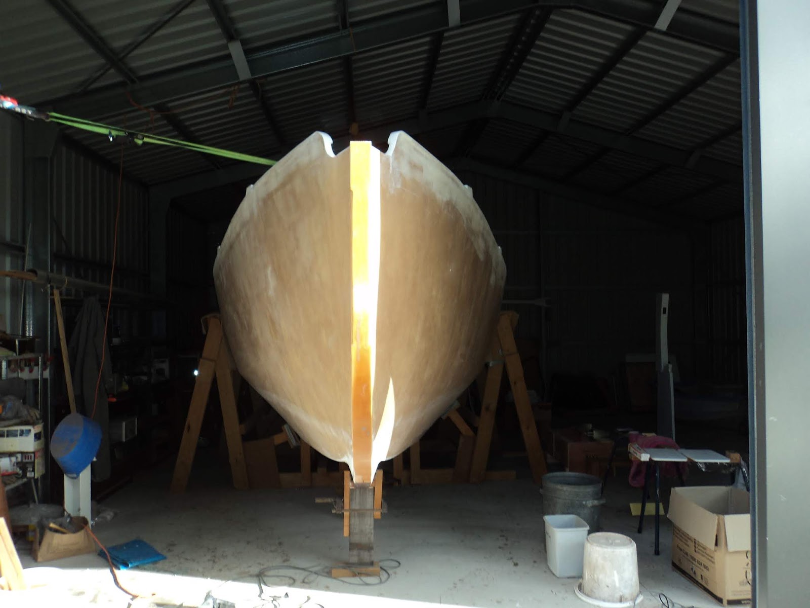
We are now almost up to date.  I have cut a slot in the bowsprit and fitted it over the stem fitting with the aft end bolted and supported into the fitting in the anchor well.  Photos to follow.

2019 will be launch year, I am running out of jobs that I will do myself.............

Scary.

Aug/Sept update Underwater Seal and paint

I've been slowly working along, not often with lots to show for it.  With the non-slip in place I drilled holes through the deck and hardwood pads for the stanchion bases.  Due to the angle of the bases the inboard two holes are through bolted with 6mm stainless bolts, the hull side two holes are two inch 14G stainless steel screws. 


I have also permanently mounted the portholes on each side.  Unfortunately the inside surrounds did not fit properly as they came in two halves and because of the thickness of the cabin side left a gap when positioned.  I ended up getting six 3mm thick aluminium rings CNC cut for just over $100 and drilled them myself to fit which worked out fine. 


Below you can see the port side stanchion and bases in place (see below for the silver underwater seal).


As I was doing this I was running electrical cables inside and attaching fans, charging points and lights.  The under waterline seal consisted of epoxy sealer/undercoat first (several coats), the same as above the waterline.


And aft:


This was followed by International Primocon (numerous coats).  This is in place of the topside paint and is aluminium based I believe and compatible with anti foul paint that will be applied just before launch:


And aft:


I've added the top rudder support, and attached the exhaust transom fitting along with the scupper covers for the cockpit drains.  You can see the four holes for the fitting just above the hole in the transom for the tiller.


The last part of September was starting on the rubbing strakes.  I laminated these from one layer of 10mm pine and one layer of hardwood, top ones are 70mm wide and the lower ones 40mm.  I put a third layer of 10mm hardwood where the chain plates will go to allow for adjustment to make them sit against the hull.

Below is the port side lower one epoxied and screwed in place drying with tape underneath to prevent it sticking to the hull.  You can see the third layer comes aft to halfway down the cabin, the clamps are helping keep them all aligned.


Jumping forward a bit here are the two port ones off with sealer/undercoat on the inside.  Right one is the longer deck edge one, more on the mast next.


Next post mast work.

Tuesday 17 July 2018

Deck dressing and keel fairing

With three top coats all round the final paint is done on the hull.  I had a short break away with the family for school holidays, back refreshed now.

When I was painting the hull sides/deck it took longer to tape and strip all the edges than it did to actually paint.  Below is looking forward when I was painting the deck, the majority of the deck got non slip after this.


And looking aft:


Once the final coat was dry, it was time to do the same with kiwigrip non slip.  First job was to tape up the edges (again).  Bought four litres, watched a few Youtube videos from the company and others applying it and away I went.  Below is the non slip area taped out, stb side looking forward.


And the front deck underway:


And working my way aft down the port side.  Not much time for photos, too busy trying not to stuff it up.


Peeled off the tape as I went, it is very viscous and didn't run.  Once it was dry it looked like this, it is hard to make out in normal light but feels good underfoot.


And a close up of the stb deck looking aft.


I later went back and did the cockpit and anchor locker.  Below is the cockpit floor taped up, left side is forward.  Not sure if or how much of the cabin top I will do.  I think I will wait a bit and see, still drying so I haven't taken photos of it.  Anchor locker is almost invisible because I left the weave of the fibreglass visible under the paint.


Once the deck was done I started to think of putting things in place for the last time.  Only got as far as the deck locker lids and the covers for the cabin vents, but it felt like a step towards dragging this thing out of the shed.


And a close up of one of the locker lids.  Stainless steel screws and hinges, rubber tie down strap.


Other than that I have been slowly finishing sanding the keel prior to epoxy sealer and then undercoat.  In the meantime I have been having a play at making some handrails for the rear quarter deck forward to the end of the cockpit combings.

Uprights and top rail are 35mm Tasmania oak hardwood, and the lower cross brace is 25mm Merbau/Kwila.  Uprights are notched into the top piece using a 35mm spade bit and then epoxy glued and screwed in from the top with 14guage x 1 1/2 inch stainless steel screw each side.  Smaller cross piece just glued.


Close up of the smaller cross brace, before sanding.


The feet are 20mm x 70mm hardwood, again cut out holes for the uprights to sit in for epoxy glue.


 Below is one with the epoxy drying.  I put temporary screws in through the bottom of the feet to hold it together which were later taken out.


Below are the two rear ones sitting in place on the quarter deck after some adjustments to the base to get them to sit as close as possible to the curved surface.  The plan is to continue another section forward each side to meet the rear of the cockpit combing.


The upright for the front section will be bolted through the combing edge on the outside.  I have drilled the holes each side oversize and filled them with epoxy, I will then drill out 8mm holes for the threaded rod.  I am glad I left a section of the combing hanging over, hopefully will work out!


And a photo of the uprights before I epoxied in the threaded 8mm rod.  Drilled up into the wood 80mm and left 30mm out to pass through the coaming (20mm wood) and leave enough for a washer and galvanised nut.


I have ordered some butyl tape and when it arrives will fit the portholes and locker access lids in the cockpit.  That should look like progress, and I will continue with the handrails and prep for keel painting. 

Thursday 7 June 2018

Second coat on hull sides and photos electrics and deck

I put the second coat on the two curved chines of the hull, and with better weather and light took a few photos to show what yesterday's post was talking about.

First off, the starboard side house battery storage, this is looking aft into the foot well that goes under the cockpit/combings.  The battery is held in with metal strapping which is screwed to the frame forward and tightened with a wire railing tension fitting as the space is not big enough for a battery box or tie downs.  Note holes aft for ventilation.


The following photos show the minimalist internal electrical fit out.  Tablets, laptops, and other devices are so mobile it doesn't make sense to me to wire in permanent items.  All lights are LED.  This is the main cabin, light each end of the seat with double USB changing port above open shelves where you can put your phone/device in while it charges.  The lights cannot be seen when standing in the cabin, hopefully will light but not dazzle.  Both swivel back to allow focus of light, I will not be having an overhead light on the roof of the main cabin.  I didn't want to run a wire across the roof to one, but can always do it if I change my mind.  Might put a red light each side down below the seat front down the track if I think I need them for night use.


The port side of the forward cabin showing the double USB charging point followed by reading light.  To the right of the second overhead storage locker you can see the fan.  Second photo shows it better.


And further forward showing the fan.  There is also a large light behind the beam just above the fan in the middle of the cabin roof.  You cannot see if from the entrance to the cabin but should light up most of the berth.  Once the power is on I will do some tests and show the results.


And the head/desk area with a larger light and a small adjustable map light.


I also took a couple of shots, first off the cockpit looking aft with three coats


And from the side, hole forward is the breather for the diesel tank with is underneath the cockpit floor level directly below the bridge deck.


And the cabin sides and top looking aft.


One with the second coat of the hull down the port side.


And just for fun I sat a few stanchions in place to get an idea of how it will look.


Painting continues, one more coat of epoxy sealer/undercoat the re mark the waterline and start undercoat/topcoats.

Wednesday 6 June 2018

Electric fitout, engine lift and painting

I have been slowly progressing, but you wouldn't know it from the lack of posts.  This will be a bit of a catch up, I will break it down into the three areas I have been working on individually but not all have photos at this stage.

Electrics

I thought I had taken photos but it turns out I didn't so a few lines will have to do until an update post down the track.  Because the boat is tied to the shed and partially unsupported I don't want to get up and inside it to take photos until all the cradle is back fully in place. 

So far I have:

  • Installed two 105AH Absorbed Glass Mat Century Deep cycle batteries, one each side underneath the berths that go back under the cockpit.  I tried a few different places but that was really the only place they would fit easily, and ran the cables to wire them up,
  • Installed in the front cabin on each side a fan, reading light and two plug USB charging point,
  • Installed in the head/desk area an overhead light and a small map light,
  • Installed in the galley a light over the stove/sink area,
  • Installed in the main cabin on each side under the storage lockers two lights (fwd and aft) and another two plug USB charging point,
  • Ran wiring and wired up all the above on two lines (one down each side of the boat) with the port one also continuing aft and under the fuel tank around to where the panel will be.
  • Ran a thicker cable for a fridge from the panel location around to underneath the seat near the galley
  • Ran two dedicated lines from the panel location around to under the galley and up near the compression post to go out to meet the mast for nav/all round white lights, and
  • Ran wire for a cockpit white/red LED light.
Photos to follow to make the above make sense.

Engine

I have been talking with the bloke who is helping me install the engine, working on a time for him to bring out his worker to show him around what needs to be done.  He is gathering commercial fuel filters, shaft fittings, prop etc in the interim.

With my brother in law I lifted the engine into the boat.  First we ran a three to one pulley up on the roof of the shed with the running end attached to a 4WD with a winch.  With the weight of the engine around 95kg each part of the rope was holding a bit over 30kg.


As the weight came onto the ropes we used another one to the side of the shed to keep the engine from touching the hull.  The 4WD winch allowed slow adjustment and raising.


Once higher than the combings we pulled the rope toward the centreline and lowered the engine down onto a board sitting across the combings. 


Then we could move the pulley on the roof of the shed and lower the engine down onto the engine beds.  I had to countersink the bolts forward of the feet to allow it to go into place, once that was done the blocks you can see underneath it were removed 


Painting

The epoxy sealer undercoating continues, I now have three good thick coats on the underside of the hull and up top on the anchor well, deck, cabin sides and top, cockpit and rear quarterdeck.  The coverage looks good, and I am happy with it to date (photos to come, sorry!).

Once I had those three coats on I could put the supports back under the boat and remove the sides of the cradle to allow the curved chines to be painted.  I have now completed the first coat, with another two to come.  I underestimated the surface area of the hull and need to get more sealer, but I think three coats will do.  It will then have undercoat (maybe two coats) and topcoat.

Below is the front before, note the straps front and rear back to the shed.  There are also extra supports each side underneath the middle of the hull:


And after:


On the port side before, note both existing props under the hull with an extra one in between:


And after:


And from aft looking forward:


I have a few more but you get the idea.  This is only the first coat as I said, and it is covering well.  I will sneak in for a few internal photos of the electrical work before the painting is done. 

Still to do for the painting:
- finish epoxy seal two more coats
- mark the waterline again
- undercoat/topcoat above the waterline
- undercoat below waterline, which will be a light grey.  Should make the hull look good.

I'm back in the groove with the roller, and feel like I am getting closer to putting the hatches and some deck fittings on.  Once it looks like a painted boat of course.