Saturday, 13 October 2012

Gaff and Boom Part 2

Managed to keep going with the gaff and boom.  Once the boom jaws were finished I painted the whole thing and attached the jaws with three 8mm galvanised cup head bolts.

Below is a close up from below, there still needs to be leather around the inside but I will get to that:


And from a distance.  Overall length is 4250mm plus the end of the jaws, but is surprising how light it is.


Then I followed the same process with the gaff.  First I cut and shaped the jaws, this time from Qld Silver Ash hardwood.  Then a cut in the main part for a pivot piece (3mm plate).


Below is with them sitting in place yet to be attached, a curve was also made in the end of the gaff.


And an overall shot, length is 3300 plus jaws.


Tuesday, 25 September 2012

Gaff and Boom Part 1


Before starting the mast I had laminated the Oregon for the boom and gaff.  Below is the gaff being laminated from 60mm x 30mm Oregon with a little shaping, 3300mm long plus jaws.  The boom is 4250mm long plus the jaws, two laminations of 90mm x 32mm Oregon cut to shape.


I drew and cut the boom jaws from spotted gum.


Then drilled the boom to suit.  Below is dry fit only, to be bolted with 3 9mm bolts and some leather on the jaws after that.  The gaff jaws are still to come.


Back from a break - Mast started


I have had a little break, putting the frames up went much quicker than I thought and had to order more wood for the chines.  This is all 25mm x 20mm, but I now have to scarf/join them all together so I end up with 34 pieces each around 8m long before I can start fitting them to the frames.  That part has me a bit worried, the build guide says take your time because the hull will show the bumps if you don't.  

So I decided to make something else instead.  Ordered some Oregon Pine, some spotted gum hardwood and away I went.  The main section of the mast was ordered and delivered, a 100mm diameter, 3mm wall thickness tube of marine alloy 6500mm long.  It weighs 16kg, and is easily carried by myself, and makes the whole thing a lot easier to build.

The top and bottom pieces are hollow to save weight.  For example, to make the bottom get two pieces of 120mm x 40mm and sandwich two 40mm x 40mm pieces each side leaving the centre 40mm x 40mm space empty.  For the top you use 100mm x 30mm. 

But you need to add strength in places and to cap the top and bottom.  This requires extra 40mmx 40mm pieces in the otherwise empty middle.  The top and bottom, and where important strength is required you add 40mm x 40mm pieces, 400mm long for mast fittings and the mast pivot at the bottom.  The end result is two semi hollow boxes, the bottom 120mm square and the top 100mm square.

Overall length of the mast is 9800mm which is longer than my shed.  

Below is the base of the bottom piece, that will have a pivot fitted and go into the tabernacle (800mm high metal mast support on deck):


And showing the length.


And after final shaping.  I cut down the upper section to fit inside the alloy tube, it is 1200mm to the flat surface the tube will rest on.  The outside hardwood pieces (small) are vertical legs for the boom support (see later photos).

The top wooden piece is 2400mm long, 300mm of that to go inside the tube.  There are two positions for rigging hardware, so it maintains the 100mm width for strength for the first 800mm.  However I planed large sections off the corners to end up with a hexagon shape, I was too lazy to go for a circle and the added benefit I see is a flat surface to bolt the rigging fittings through both sides.  The final 1300mm tapers from a 100mm wide hexagon to a 70mm square

I was adding internal plugs for the top and bottom, and supports at each of the two rigging places so I decided to make some adjustments.


As I needed to run wiring down the mast, I planed a corner off each of the inserts to leave a space for this.  


I also cut the tops of each insert on an angle down to the gap, thinking that any water that gets in through the mast top or rigging bolts will run down and eventually out where the bottom of the pipe meets the wooden base where the electrical wire will run.


Below is the view down from the top.


 Epoxy it all together:


 With the mast top platform sitting on it.


A bit of sanding on the inserts to get them sliding into the tube and then on to finish the boom support.  Below is 3 layers of 9mm ply that will be screwed to the small hardwood uprights shown earlier.


.

Sunday, 19 August 2012

Lessons learnt from frames to strongback

I will add to this as I think of more but so far:

Follow the plans exactly - I saved some wood by not continuing the solid frame sides up higher to attach the temporary cross piece.  This cost me lots of time, heartache and extra work in the long run as I had to buy more wood to support them higher.

Mark everything when on the drafting floor - some of the frames I missed the waterline and it was a pain to try and confirm them.  It is also an opportunity for errors to occur.

Take your time with the frames - mine worked out fairly well and were level in each direction when they came off the floor.  This makes it much easier when the time comes to line them all up, and it helps your confidence no end when things start to go right.

Measure twice, cut once - everyone knows this one, thankfully I only had to remake the solid wood for one frame.

Closely related is measure twice, screw once - as I was standing up the frames and moving them up and down each side I lost count of the times I had to remove screws because I had forgot to check something.  Get it where you think it needs to be, then double check EVERYTHING before you screw it in place.

Standing up the frames - lots of clamps and take your time.  Start with the centreline on the frame matching the centreline on the strongback.  I used wire down the strongback for the centreline, then string and a weight to get the frame in the right spot.  Use string from the centreline out to the sides of the frame to confirm they are at 90 degrees (the length of the string should be the same).

Keep your level close to hand - always keep checking levels in each direction.  A little move one way can throw out other parts of the frame.

Don't forget to duck and lift your feet - as you move side to side and through the frames there are very hard pieces of wood at shin height and also some plywood stuff just at head height out of view.  Trust me, it hurts!

Eat and Hydrate - keep water close at hand and drink often.  Sounds simple but several times I got lost in the work and realised at the end of the day I was very thirsty.  I also found sometimes I needed to walk away and have a break when things were not going well.  Plus you get to look at what you have achieved so far which keeps the motivation up.

Frames standing up

With the assistance of an extra day off for the local show in Brisbane, and a rostered day off I had some solid shed time to get the frames up.  I will do another post after this one with the lessons learnt for those considering a build in the future.

But now time to gloat!

Started with frames 4 (galley front) and 5 (galley rear) as per the building instructions from John Welsford.  I spent extra time getting the frames at the right height from the strongback (1106mm) as all the waterlines etc are taken from here.  Once they were stood up you screw the 12mm ply galley front bottom piece (which is the top when you build upside down!) to stiffen the two frames.


And from the side with frame 3 in front:


Then I worked back from frame 5 to the transom.  Each frame was levelled vertically, horizontally and using a string and nail from the centreline was positioned at 90 degrees to the centreline (hopefully).  Below is 3 - 7:

Fr 3 - 7 from the front side:


Continue on to the transom which is actually 15mm above the waterline (below when building upside down) hence the packer under my string line to get levels right at the sides.  In front you can see frame 10 and 9 which is the solid one:


And from the side:


Once I got the transom done it was time to dynabolt the wooden ground supports for the stem and frames 1 -2:


Then I stood up frames 1 - 2:


You will see in the below photo some extra legs.  One of the lessons learnt is to follow the plans exactly.  Some of my frames needed to be raised above the cross pieces, but this actually worked out well because I could put in a vertical leg to take some of the weight and also support the frames:


Then this morning it was finish attaching frame 1, then cut the stem and glue.  This took much longer than I thought.  Below is the cut down stem:


Glued in place:


And from the side:


Once they were all up, I went along and nailed them to each other, across the tops and back to the strongback in a few places.  This took a while as I was checking everything again, below shows the ones across the top, the earlier photo of the legs shows one of the angle ones in the background:


And now, the final results.  Thanks to digital photos I can spin them round to right way up for the internal shots.

From a distance from the front:

Inside from fr 8 towards fr 1:


Frame 5 - 1 inside

Frame 6 to the transom:


Now have to organise the wood for the stringers.

Sunday, 12 August 2012

Strongback

First was the side pieces which were in two pieces each, joined with blocks inside and out and four 8mm bolts/glue per side. 


Then I clamped them close together and marked out all the places for the cross members for strength, marked the position of the legs and also the frames (measurements adjusted for my stretch).


Then I clamped all the cross members in place and screwed them into the sides with 70mm tech screws (two per side). This gave me the basic frame. 


Then I cut 10 legs 400mm long, and while upside down clamped them in place four at a time. I then checked the level each way including the ones already done, sideways, horizontally and also diagonal. I also checked each leg for level. Then I crossed my fingers and bolted them all to the sides with two bolts per leg.

Once I had finished all the legs, I flipped it over. 


A further two tech screws were put in per leg where the leg was underneath the cross pieces. This was at each end, and one of the legs in the middle.   The final step was a 9mm ply end piece glued and screwed to the legs each end, the sides and the cross piece.  There is one of these on each side at each end to provide bracing.


From the side below, four tech screws 70mm long from the top, two 8mm bolts from the side through the leg and side piece, plus the ply and screws/glue from the front.  Hopefully strong enough....


The final check was level along each of the sides at various points, then each of cross braces. Below is the result, with help from my assistant (and the blokes who laid the level concrete slab for my shed, I owe them a beer).

Side pieces:


Cross pieces:

To give me an excuse for a beer, I stood up frame 3 ( it is too low but looks the part!).


Onwards to standing up the frames, have to borrow a laser level.

Transom finished.

Transom is done, no more frames!! This one finished above the waterline.

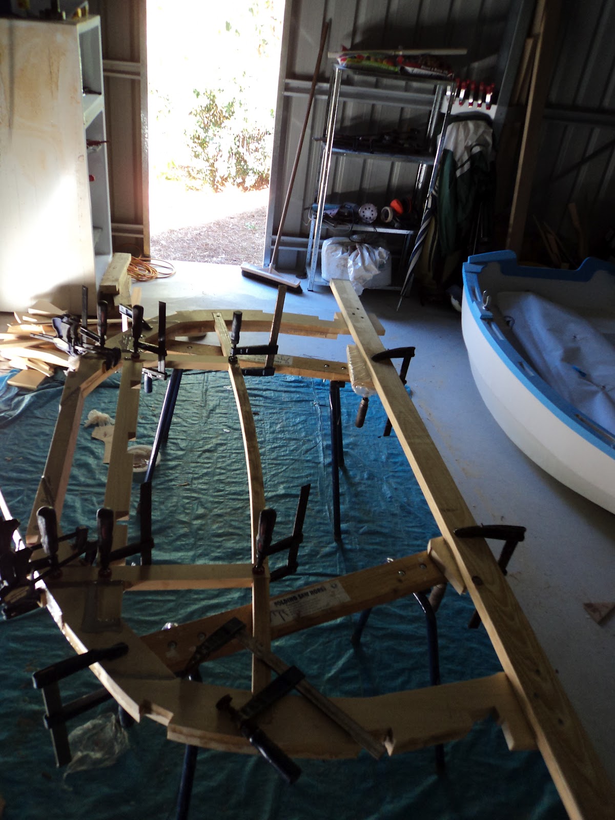
The frame has a doubler on the forward side, a 30 x 45mm cross piece to support the cockpit floor (half lapped into the frame so the transom has one flat vertical surface for the ply transom) and two vertical 30 x 45mm pieces for the seat front support. The laminated beam is only dry fit at this stage, and there is another laminated beam to go across from the very top for the aft deck.


Once the cross piece was done, the vertical supports for the seat fronts were positioned.


This is a close up of the solid frame, horizontal and vertical pieces all half lap joined. All epoxy glued in place, I skillfully left nice spaces in the joins to allow the epoxy to get a good penetration! They are not as bad as they look, trust me.


It was glued with everything in place, but not all was glued.  The laminated beam to the frame and the laminated beam to the upright were not glued.


This is the final result from forward side:


And from aft, all flush finished so the ply can go on.