Tuesday, 8 October 2013

Keel continued

Last post I had just attached the wood each side of the stern tube and filled the hull join with epoxy.  Next step was to build up the rear and front until the keel was level along it's full length for using the long kwila planks.

Below is building up the front, note the string level.  This continued on the front but I didn't get photos because of a mad rush to glue it all down, more on that later.


Down the aft I managed to glue the threaded rod in early you will remember.  To overcome this I came up with a cunning plan. First I drilled some 10mm holes in four bits of wood.  Each was placed over one of the rods, and then cross pieces screwed between them, with the edges of the cross pieces lined up with the edge of the keel wood underneath.  Finally long pieces were screwed between them all to lock it all together.

I used 10mm holes for 8mm rod so I had a margin of error when I drilled the future keel wood.  Below are some photos showing firstly the drilling jig sitting in place but not positioned or clamped to drill.  MARK fwd and carefully align with the edge of the keel wood and the direction and top face, the holes will be in the wrong place if you don't place it correctly before drilling!


Close up showing how it is all secured together for accuracy:


And an after shot showing the third layer aft piece:


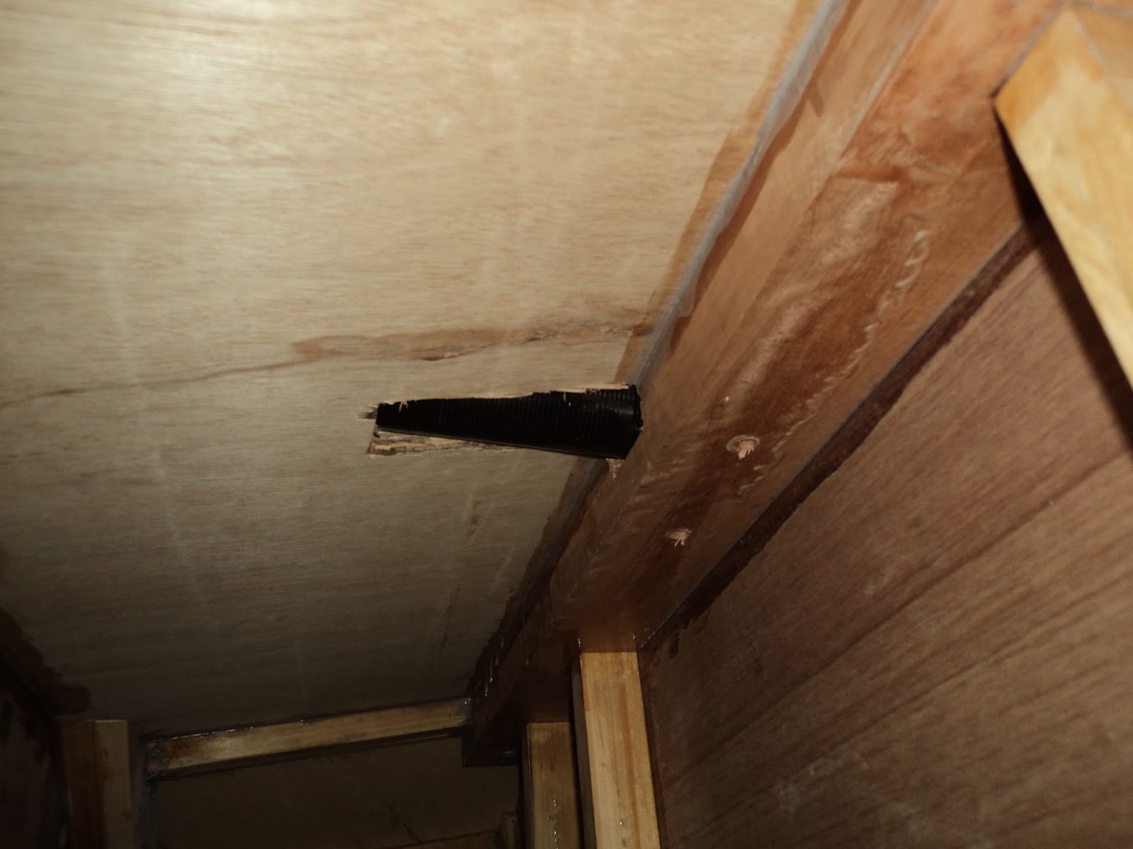
Now some shots of where I am up to, covering the tube and level to the hull (dry fit):


Same but closer and from aft:


Second of the level layers glued in place, note the forward packing pieces to make it level and angle cut for capping piece:


Still second layer but looking aft:


Level layer 3 aft glued from a distance, the next layer will go right back to the transom as the space for the propeller has been left.


Same but close up:


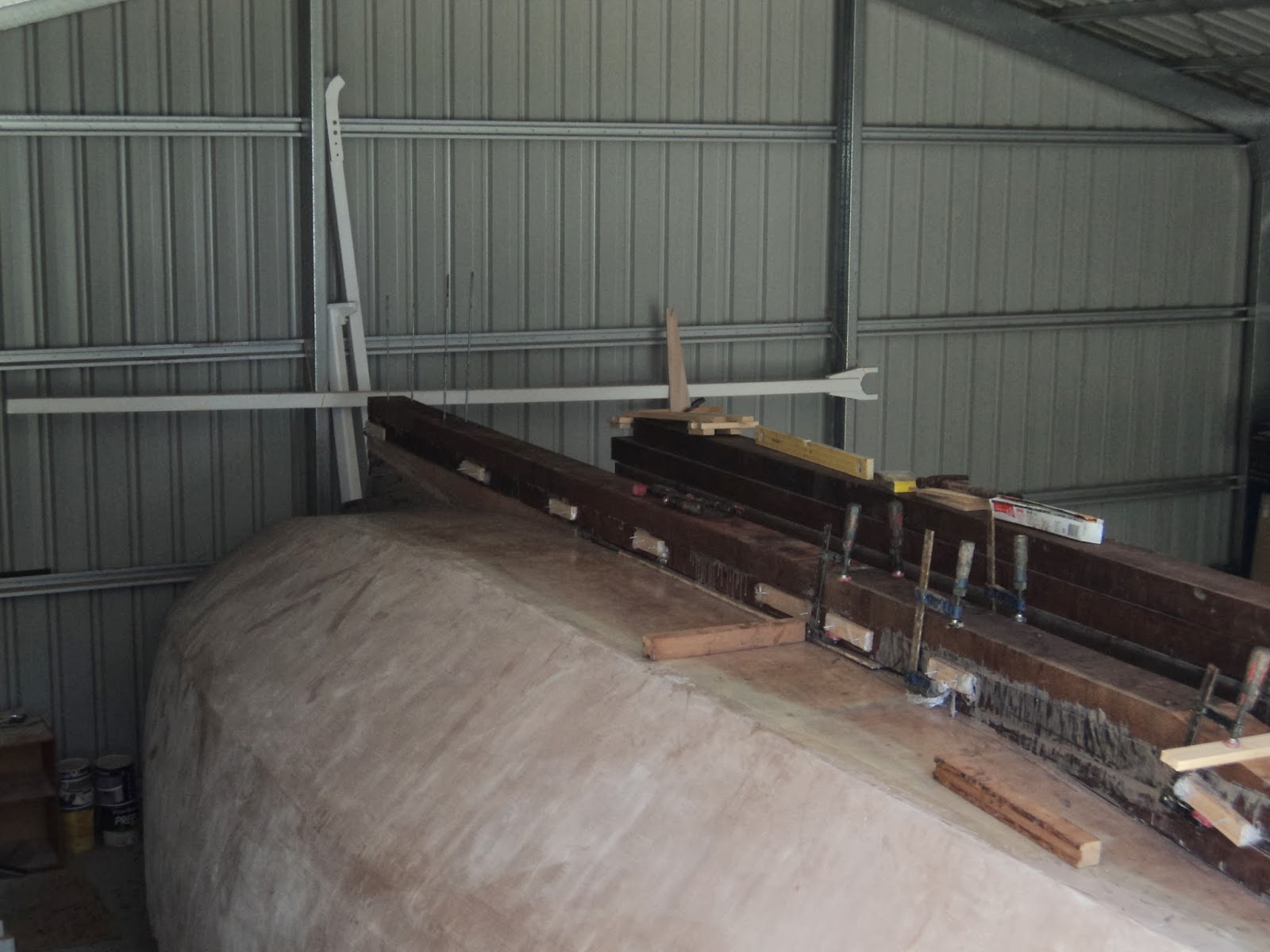
I have decided to glue up each layer as I go instead of making the whole keel dry and doing a final single glue up session.  However when I placed the first full length piece I have managed to leave some gaps between the keel and the hull due to curve in the piece and not enough weight to bend it down.   After much consideration I have decided I will glue up the remainder of the keel and after final shaping (the front and rear have to be planed down to make them thinner) I will fill the gaps with thickened epoxy glue and fillet/fibreglass tape the hull/keel join.  It may not be necessary, but I will feel better knowing there is a layer of 200mm wide tape holding it in place.  The finished keel will also be given a few layers of straight epoxy.

Onwards to more layers, final stack will be seven layers high, with the top two having a large space at the front for the lead keel.

Friday, 13 September 2013

Stern tube and support finished

After making some substantial holes in the hull for the stern tube it was time to epoxy/glue the keel underneath it and the tube itself into place.

First job was to glue up the keel underneath where the tube was to sit.  As you can see I used the threaded rod to put some clamping pressure on the keel.  I had sprayed them with silicon and thought I could get them out after.  DON'T DO THIS!  They are in there for the long term now and I had to get a spanner and wind each of the nuts all the way up and off.  They were to be permanently epoxied into the keel, just not this early.  I worked with them in place from then on and will have to all the way up the keel. 


Second job was to close off the stern tube from the inside so I could pour epoxy in from outside to fill up the gaps.

First behind frame 8.  I packed out around the tube with 25mm high by 20mm wide Hoop Pine left overs and a ply cover.  It was epoxied up first, and once dry was drilled for 14g x 30mm screws to go through the wood and up into the hull ply to hold it in place until the epoxy/glue set between it and the hull.  At the same time I coach screwed an extra hardwood cross piece across the frame to take the keel load and spread it a bit. May not have been needed but I cut out some of the original hardwood cross piece so why not!  After it dried I drilled the keel bolt holes down through it from on top.

Before:


And after:


Where the tube came through frame 8 and out over frame 7 I shaped some ply and packers (there was a gap you can see (below close up) where the ply of the frame did not go all the way to the hull at the top) and epoxy/glued and screwed it over the hole.  Thick epoxy/glue was pushed up over the top of the tube to seal up completely.

Before (bad shot earlier sorry):


After from a distance:


And close up:


Then I used lengths of 50mm x 50mm hardwood packing pieces to sit each side of the tube on the keel support to match the 150mm wide bit underneath.  After drilling holes and trimming the wood to length I epoxy/glued them in place.  A nice thick bed underneath the side pieces of wood means that later on I can fill the gap around the tube without the epoxy running out.

I did put a bit of epoxy in around the tube but it did not have glue powder in it so was very running and went out.  Concentrate on just having a thick layer under so you can tidy up the outside and have a good squeeze out on the inside beside the tube.  Last thing to do was to sit on top and pour normal epoxy down where the tube goes into the hull.  Because the inside was sealed, as it ran inside into the hollows I just kept topping it up slowly.  Leave a bit of time between as it runs in for the air to get out and keep topping up until it is full.

You can see the straight mixed epoxy on the right has hopefully filled all the support box (shown earlier) behind frame 8 and up to the top where the tube leaves the hull:


Whilst the epoxy was setting I used scrap nailed to the keel to help clamp down on the 50 x 50 wood each side.  I also placed a large piece of 150mm keel wood sitting across to hold that in place near where the tube went into the hull.  I used epoxy/glue powder to fill in where the tube leaves the end of the keel and a small amount down the other end near the tube/hull entry.  The remaining space will be filled when I finish the keel.


A final shot from the side, note the lighter scrap used to clamp onto:


Apart from gluing a bit down the front until it is level, the remainder of the keel will be build up 'dry' and then assembled/glued down once it is all ready.  Once level as close to the 3600mm full lengths will be used.

Next is to build up the front at the stem cap to level.

Friday, 6 September 2013

Keel hardwood and stern tube fitting

First thing to organise was the keel wood.  11 pieces of 150mm x 75mm kwila that were 3600 long.  These things were VERY heavy, craned off the truck but then carried in one at a time by me.  Hope the strong back lives up to its name!


I mentioned in the last post the stern tube I am fitting through the keel.  First step was to mark on the hull where the shaft line hit the hull using the drawings.  Then I started dry fitting pieces until the tube was supported from the hull to where the propeller will be.  From the inside I drilled up for the temporary threaded rod.

I used a piece of PVC pipe the same diameter as a guide as I carefully chiseled out a sloped hole through the glass/ply hull.  Once through and widened until the pipe fit (required inside and outside work so I didn't destroy the inside ply face)  I found it was going to pass through the hardwood cross piece on the bottom of frame 8.  Once I had made a start I drilled a 10mm hole through the hardwood using the sloped cut as a guide so I could work from both sides of the hardwood.  After much time and repeated climbing from inside to out and back again I could slide the 2000mm pipe up from the inside.

Below is a shot showing the slot in the hull as I pushed the tube out from the inside:


And an overhead shot showing the pipe lying (hopefully) on the centre line of the keel and into the hull:


A side shot of the same, my drilling of the holes was a bit angled and cramped inside of the frames.  If necessary I will cut off the rod as the keel gets higher and drive some drifts (I think they are called) from the top down as these rods will be permanently epoxied into the keel:


An inside shot from the side showing the path of the tube through the hardwood on frame 8.  It is probably not needed but because I have cut some of the cross piece out I am going to put an extra piece of hardwood across the centre line 300mm each side to spread the load from the bolts.  Basically epoxy/coach bolt a doubler of hardwood over the top:


And a slightly out of focus shot showing the engine end of the stern tube sitting over the top of frame 7:


Next is to build wooden supports on the inside of the hull where the pipe is located so when the whole thing is epoxy/glued in you can fill the whole lot up.  That will be in the next post along with epoxy/gluing the first bit of the keel in place first.

Friday, 23 August 2013

Stem cap and keel holes

After plenty of looking at the inside, measuring, checking with a plumb bob and marking it was time to drill holes up through the frame hardwood cross pieces and through the bottom of the hull.  I also ran a string down the centreline on the outside and marked it with permanent marker.

The keel will be 150mm wide hardwood, the most important holes are the ones in frame nine and ten which will pass each side of the fibreglass tube the propeller shaft will run through.

Below is a picture of the fibreglass tube, 50mm external circumference:


Also made up a template of the keel, I am thinking steel keel box filled with lead ingots at this stage:


Took some deep breaths, used a square and the frames to try and get the holes as vertical as possible and drilled them.  Ones at the front and where the keel will go are 10mm, down the aft 8mm.

Frame 2 10mm hole:


The stem was laminated at the start of the build and incorporated into the hull with stringers and finally planking.  Now that the sides are done it was time to cover it with hardwood and continue it up over the bottom where it will meet the keel.  I got 90mm wide strips delivered, plan called for 5 x 5mm but my supplier could only do 8mm.  Final result is still 24mm or just short of an inch thick so I think it will be okay.

A piece of hardwood was needed to fill in a space where the ply bottom finished (had to meet a hardwood cross piece at the other end of it).


Nails were removed once dry, the front (left as you look) planed down to an angle.  Managed to plane a bit off the end of my finger but only minor.  Made me pay attention though, it has been a while since I used the electric plane.  Then the first layer went on.  Started to pull down the high end to the right angle, snapped it in half at the bend.  After a panic attack I realised I would have to use the snapped piece in the middle of the three.  I had previously seen on the woodenboat forum (where I get all my boat building advice from!) about bending wood.  Marked each end of the curved area, wrapped it in a hand towel and poured boiling water over each side and let it sit.  After a few minutes while still hot bent it around the curve, screwed in place and left it for the epoxy/glue powder to set.  Worked a treat.


Cut a fill in piece of hardwood to fit on top of the first to support the cap, pulled it down with a strap and the second layer went on in two bits, join is about half way so that the curve and top is one piece.  Wrapped some cling wrap over where it will be layered into the keel, you will understand later.


Then the final piece:


And in close up, note the extra hardwood packing piece:


Filled the screw holes (screws were removed once each layer had set and re used so there are no screws in the cap anywhere) and blended the hull join with filler powder.  Checked my drawings and plans, and cut off the cap.  After a bit of sanding and clean up this is the result:


Close up, the cut out bit is where I had the cling wrap so the first and second layer would not stick together:


Cap to hull filled and sanded:


And looking back along the hull.  Don't worry about the lean on the back threaded rods, it is 8mm rod in 10mm holes so there is a lot of movement.  The first one is 10mm rod in 10mm hole and is standing nearly perfectly.  I am sure they are not perfectly level each direction though I must admit.


Fairing part two

Once I was sick of the first side I started on the second.  It didn't seem as bad and I think some of my early coats on the first side were too thick and ran so much that I was just wasting epoxy/filler, time, energy and sanding paper.

The second side seemed to benefit from the early mistakes.  If you remember on the bow I tried to use a notched spreader to make grooves with only partial success.  After sanding and filling I stuck with the thin coat, sand, recoat process which seemed to work okay.  Maybe I was just over it and decided it was good enough.  I have moved on to the keel prep and start (next post shortly) and haven't taken any shots of the second side.  It looks like the first, see below for the final outcome.  I may go back as I work on the keel and do small spots if they bug me, but we will see.

Looking down the first side after final sanding:


Looking from the side at the transom towards:


Looking aft at the top curve:


Lastly looking aft bottom curve:


Next post will be prep for the keel with holes drilled through the bottom and building the hardwood stem cap.

Thursday, 1 August 2013

Fairing part one

Had a few computer problems so have not updated for a while.  The fairing of the hull continues, this would have to be the worst part so far but I am getting there.

After the first layer of epoxy/filler powder was dry I started.  First I made a sanding board so I could sand the curves.  These are also known as torture boards, and with good reason.  The ply is 6mm so I can bend it around the curve, I cut slots near each end to feed in sandpaper from a roll and screwed extra ply on top to hold it in place.  Couple of handles screwed on and away I went.  The idea is you sand in different directions/angles and the bend in the ply stops you sanding flat spots because it will take the curve of the hull as you press in on the handles.


I also have another sanding block similar to a bricklayers trowel with a handle, very useful as well.

Although I thought the hull was quiet smooth I soon discovered all the little dimples in the hull.  The pattern of the fibreglass mat, even though I coated it a number of times, was still there.  I tried using a notched spreader with the epoxy, the idea being you sand it hitting the high points and then fill in the hollows.  I didn't mix the epoxy thick enough and it ran together instead of leaving peaks.  Luckily I only did the front on one side as an experiment.  I'll let you know because it is on the second side I've just started. 

After starting sanding the entire hull and putting on a second coat I decided to work on a single side at a time for my mental health.  That way I could see progress as I did each coat.  I have left the bottom until after I have made the keel.

This the side I did first after sanding:


The other side:

The next coat going on:


Sanding and re-coating a couple of times I found a thin layer scraped with a wide plastic spatula was better than doing thick coats which ran and needed lots of sanding.  This is the front:


And looking towards the transom:


I still have a few spots to sand after today, I had a bit of mixture left over so went back to a couple of small hollows.  The above photo was when it was still wet, the shine goes with the final fine sand.


The other side which I am now working on, this is early sanding:


 And the most recent layer today:


And looking towards the transom:


I will continue on sanding and layering, and will continue with the next post including final shots.  But this takes a while!